2026 Best Guide Why Are Tight Tolerances Critical in Parts?

Time:2026-11-22 Author:Charlotte
0%

In precision manufacturing, a part can look flawless and still fail to fit. A shaft may bind in a bearing, or a sealing face may leak when dimensions drift beyond specified limits. That raises a practical question: why are tight tolerances critical in engineering parts? They help components assemble, move, seal, and carry loads as intended, especially when parts come from separate production runs.

A tolerance defines the acceptable variation around a specified dimension. It does not require every part to match one exact number. Engineers set limits by considering function, material behavior, machining processes, and inspection capability. A clearance fit needs room for motion; a press fit needs controlled interference. On a precision spindle, a few micrometres may affect runout. A protective cover may work reliably with a wider range. Context matters.

Tighter is not automatically better. Smaller limits can increase machining time, tool wear, inspection effort, and scrap risk. Specifications are sometimes copied forward without checking whether the assembly needs them. That deserves a second look. This guide explores how tolerances influence fit, interchangeability, durability, and quality. It also covers measurement tools, common drawing errors, and practical ways to balance precision with cost. A micrometer or coordinate measuring machine can verify dimensions, but measurement plans must match the feature and required accuracy. The aim is dependable performance, not precision for its own sake.
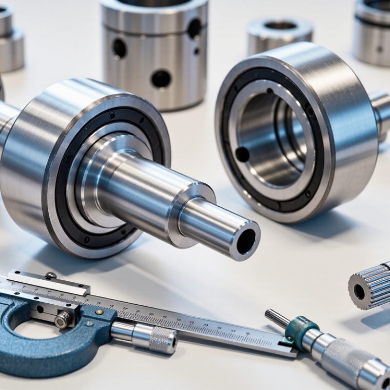
2026 Best Guide Why Are Tight Tolerances Critical in Parts?

What Tight Tolerances Mean: ISO 2768-1 Sets ±0.1 mm for 3–6 mm Parts

What Tight Tolerances Mean: ISO 2768-1 Sets ±0.1 mm for 3–6 mm Parts

A tolerance defines how far a finished dimension may vary from its drawing value. Under ISO 2768-1:1989, the medium class allows ±0.1 mm for linear dimensions over 3 mm up to 6 mm.

A nominal 4.00 mm feature may therefore measure from 3.90 to 4.10 mm. That is a 0.20 mm total window, not a promise that every part will measure exactly 4.00 mm.

The standard also lists different limits for other tolerance classes, so the drawing’s stated class matters.

Consider a small pin entering a drilled hole. If both dimensions drift toward their permitted limits, the fit can become loose or difficult to assemble. Tightening every tolerance may seem safer, but it can raise machining and inspection effort without improving function.

ISO 14253-1:2017 addresses conformity decisions when measurement uncertainty matters; a reading near a limit may not be a clear pass or fail. Check the measuring method, too. A caliper’s resolution and handling can affect confidence in a small-part measurement.

One detail is easy to overlook: general tolerances are a fallback, not a substitute for specifying critical features. ±0.1 mm is useful context, but not a universal design rule.

How Tolerances Define Fits: ISO 286 Classifies Sizes from IT01 to IT18

ISO 286 uses IT grades to describe the size tolerance allowed for a feature. The scale runs from IT01, among the tightest grades, through IT18, among the coarsest. A lower IT number means a narrower tolerance zone, but the actual tolerance value also depends on the nominal size. A shaft and bore with the same grade may not have the same permitted variation.

That difference affects assembly. For example, a shaft near the upper end of its size range may bind in a bore near the lower end. Engineers choose tolerance zones and their positions to create a clearance, transition, or interference fit. Small numbers matter. A bearing seat may need close control to limit movement, while a non-critical cover can often accept a wider range. Tighter is not always better.

On a drawing, the basic size and fit designation guide inspection and production. A machinist might check a bore with a calibrated gauge, then verify borderline parts with a measuring instrument suited to the required tolerance. Temperature, tool wear, and measurement technique can all affect readings. Real parts are less tidy than a chart suggests. It is worth reviewing whether each tight tolerance serves a clear function, since unnecessary precision can increase scrap and machining time.

Why Precision Matters in Assembly: GD&T Controls Position with Tolerance Zones

In an assembly, a hole that shifts slightly can make a fastener bind or leave uneven gaps. Tight tolerances help parts fit as intended, but precision is not simply about making every dimension smaller. GD&T communicates how much a feature may vary and how its location relates to defined datums. This gives designers, machinists, and inspectors a shared way to evaluate the same part.

A position tolerance zone controls where a hole’s axis may fall relative to the specified datums. For example, a cylindrical zone can allow the hole axis to move within a clear boundary, rather than judging its location from separate coordinate dimensions. This is useful when several holes must align with pins or mating components. Small errors add up. Still, an unnecessarily tight zone can increase machining time, inspection effort, and scrap without improving how the assembly works. Choose the tolerance based on function, process capability, and the actual fit required.

Tips: Confirm the datum scheme matches how the part is located during assembly. Check a sample part with suitable inspection equipment, and review the results with the manufacturing team. If a fit problem appears, revisit the design assumptions; the first tolerance choice may not be right.

Why Tight Tolerances Matter in Assembly

Illustrative inspection sample: radial hole-position error compared with a GD&T positional tolerance zone of ⌀0.20 mm. The maximum allowable radial offset is 0.10 mm; exceeding it can affect part alignment during assembly.

How Process Capability Is Assessed: Cpk 1.33 Is a Common Production Benchmark

Cpk, or process capability index, shows how well a stable process fits within its specification limits. It considers both process variation and how closely the process average sits between the upper and lower limits. A Cpk of 1.33 is a common production benchmark, but it is not a universal guarantee of part quality. The required level depends on part function, customer requirements, and the consequences of a dimensional failure. Small differences matter.

To assess Cpk, collect representative measurements while the process is running under normal conditions. Check that the measurement system is suitable and that the process is stable before interpreting the result. For example, measure a machined shaft’s diameter across multiple production runs, not just a few parts from one setup. A high Cpk can look reassuring, yet misleading data or a drifting tool may hide risk. Teams sometimes rush the study; that is worth correcting. Record the sample size, operating conditions, and any adjustments made, so the result can be reviewed and repeated. If the data do not follow a roughly normal distribution, a conventional Cpk calculation may not tell the whole story.

2026 Best Guide: Why Are Tight Tolerances Critical in Parts? — How Process Capability Is Assessed: Cpk 1.33 Is a Common Production Benchmark

Example Part Feature Specification Limits Process Mean Standard Deviation (s) Calculated Cpk Capability Assessment Why the Tolerance Matters
Shaft diameter 10.000 ± 0.050 mm
LSL: 9.950 mm; USL: 10.050 mm
10.005 mm 0.010 mm 1.50 Above 1.33 Controls fit with mating components and helps prevent excessive looseness or interference.
Housing bore diameter 20.000 ± 0.100 mm
LSL: 19.900 mm; USL: 20.100 mm
20.025 mm 0.025 mm 1.00 Below 1.33 A bore near a limit can affect alignment, clearance, assembly effort, and operating performance.
Locating pin diameter 5.000 ± 0.020 mm
LSL: 4.980 mm; USL: 5.020 mm
5.000 mm 0.005 mm 1.33 At benchmark A controlled pin size supports repeatable positioning and consistent assembly with its mating feature.
Part thickness 2.000 ± 0.030 mm
LSL: 1.970 mm; USL: 2.030 mm
1.998 mm 0.008 mm 1.17 Below 1.33 Thickness variation can change stack-up dimensions, clamping load, or clearance in an assembly.

How Cpk is calculated: Cpk = the smaller of (USL − process mean) or (process mean − LSL), divided by 3s. A Cpk of 1.33 is a common production benchmark, but acceptance criteria depend on the customer, application, and quality plan. The example measurements above are illustrative; capability interpretation assumes a stable process and representative data.

How Parts Are Verified: ISO 14253-1 Accounts for Measurement Uncertainty

Why Are Tight Tolerances Critical in Parts?

Tight tolerances matter when a small dimensional shift affects fit, sealing, motion, or product safety. But a measured value is never perfectly exact. ISO 14253-1:2017 addresses this by requiring measurement uncertainty to be considered when deciding whether a part conforms. A reading near a tolerance limit may not provide enough evidence either way. That distinction matters.

For example, imagine a shaft with an upper limit of 10.05 mm. A gauge reads 10.048 mm, with an expanded measurement uncertainty of 0.01 mm. The uncertainty interval crosses the limit, so conformity may not be demonstrated confidently. ISO 14253-1 provides decision rules for such cases; it does not mean every borderline part is automatically defective. NIST Technical Note 1297 explains how measurement uncertainty is evaluated and reported, including contributions from calibration, resolution, and repeatability. In practice, record the instrument, method, and uncertainty alongside results. A clean number alone can mislead. Teams sometimes overlook this.

Tips: Check calibration status, control temperature, and repeat borderline measurements with a suitable method. Agree on decision rules before inspection, not after a result causes disagreement. If uncertainty is too large, improve the measurement process rather than simply tightening the tolerance.

FAQS

What does a tolerance of ±0.1 mm mean for a 4.00 mm feature?

The feature may measure from 3.90 mm to 4.10 mm under the stated tolerance class. That is a 0.20 mm range. It does not promise an exact 4.00 mm measurement.

Does the same tolerance apply to every small dimension?

No. The permitted range depends on the drawing’s tolerance class and the dimension involved. General tolerances are a fallback, not a substitute for specifying critical features.

How can small size variations affect assembly?

A 10 mm shaft near its upper limit may bind in a bore near its lower limit. The fit can become loose or difficult to assemble. Small numbers matter.

What do IT grades tell engineers?

IT grades describe the allowed size variation. Lower grades mean narrower tolerance zones, but the actual values also depend on nominal size.

Should every part have the tightest possible tolerance?

No. Extra precision can increase machining time, inspection effort, and scrap. A wide tolerance may work for a non-critical cover. Still, function should guide the choice.

Why can a measurement near a limit be uncertain?

Instruments have resolution limits, and handling can affect readings. For example, a reading of 10.048 mm with 0.01 mm uncertainty may cross a 10.05 mm limit. The result may not clearly prove conformity.

What details should be recorded during inspection?

Record the instrument, measurement method, and uncertainty with the result. Check calibration and control temperature. A clean number alone can mislead.

What should teams do when a borderline result causes disagreement?

Agree on decision rules before inspection, then repeat the measurement using a suitable method. If uncertainty remains too large, improve measurement practice. Tightening the tolerance may not fix it.

Conclusion

Understanding why are tight tolerances critical in engineering parts starts with how small dimensional variations affect fit, function, and interchangeability. General tolerance standards such as ISO 2768-1 can specify a ±0.1 mm tolerance for certain 3–6 mm dimensions, depending on the applicable tolerance class. For mating components, ISO 286 defines tolerance grades from IT01 to IT18, helping engineers select fits that balance accuracy, performance, and manufacturing practicality.

Precision also depends on controlling and verifying more than a part’s basic size. Geometric dimensioning and tolerancing (GD&T) uses tolerance zones to manage features such as position, supporting reliable assembly. Process capability is commonly assessed with Cpk, with 1.33 often used as a production benchmark. During inspection, ISO 14253-1 provides decision rules that account for measurement uncertainty, helping ensure that acceptance decisions are consistent and that tighter tolerances are both meaningful and verifiable.

Charlotte

Charlotte

Charlotte is a seasoned marketing professional with a deep understanding of the company's portfolio and a passion for elevating its presence in the market. With a keen eye for detail and a commitment to excellence, she ensures that our professional blog is regularly updated with insightful articles......