China’s machining sector serves automotive, aerospace, medical, and general industrial production. In every workshop, cutting edges slowly lose their shape. Heat rises. Surface finish changes. Production costs follow.
So, what is the importance of tool wear in machining? It affects dimensional accuracy, cycle time, surface quality, energy use, and operator confidence. A worn carbide insert may leave a visible burr on a steel component. In another case, flank wear can push a 20-micrometer tolerance beyond its limit. The machine still runs, but the process is no longer stable.
F.W. Taylor, a pioneer of scientific machining, wrote, “The life of a tool is the length of time it will cut satisfactorily.” That practical observation still matters. Tool life is not only a replacement schedule. It is a measurable production variable. ISO 3685 provides established methods for evaluating tool life and wear, while modern factories also use vibration, spindle-load, and temperature data.
This article examines China’s top ten tool-wear factors in machining, including cutting speed, feed rate, depth of cut, material hardness, coolant performance, tool geometry, coating failure, vibration, chip control, and operator practice. The list is useful, but not perfect. Real machines rarely fail for one reason alone. A coolant problem may look like excessive speed. Vibration may disguise poor fixturing. That uncertainty deserves attention.
Understanding these interactions helps engineers select realistic cutting parameters, inspect wear patterns, and prevent sudden quality failures. Small marks on an insert can reveal large weaknesses in a process. The goal is not to eliminate wear completely. It is to control it before it controls production.
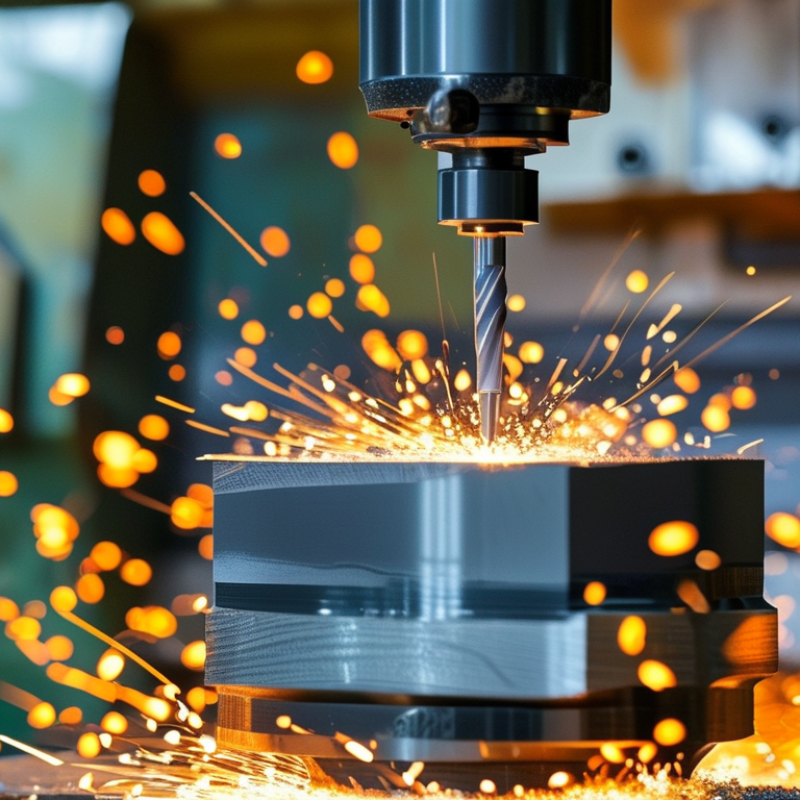
China Top 10 Tool Wear Factors in Machining: Why They Matter?
Cutting Speed and Feed Rate: The Core Causes of Accelerated Tool Wear
Cutting speed often controls tool life more strongly than machinists expect. The Taylor tool-life model uses V·Tⁿ = C, with carbide-tool values commonly ranging from 0.20 to 0.30. Doubling speed can therefore reduce tool life by roughly 75% to 94%. That range is severe. It also explains why a tool may fail after one aggressive production change. ISO 3685 commonly evaluates carbide wear near a 0.3 mm flank-wear limit, giving engineers a measurable replacement point.
Feed rate creates a different problem. Higher feed increases chip thickness, cutting force, and heat entering the cutting edge. A CIRP manufacturing review links excessive mechanical loading with faster flank and edge wear, especially during interrupted cuts. Practical trials often show that a 10% feed increase can raise cutting force by approximately 10% to 20%, depending on workpiece material and tool geometry. The exact result varies. This is where many process sheets become too optimistic.
In a Chinese machining cell, a small speed change may look harmless on the control panel. A 20 mm end mill running 20% faster can produce a visibly hotter, darker chip stream. Feed per tooth must be checked with it. Reducing speed alone may create rubbing, while reducing feed too far can worsen edge contact. Engineers should record spindle load, flank wear, chip color, and tool-life minutes together. I have seen “stable” settings fail because only surface finish was monitored. That mistake remains common.
| Rank | Tool Wear Factor | Why It Matters | Typical Wear or Failure Mode | Practical Control Measures |
|---|---|---|---|---|
| 1 | Excessive Cutting Speed | Cutting speed is the main source of heat at the cutting edge. Excessive speed can rapidly increase diffusion, oxidation, and crater wear, especially when machining heat-resistant alloys. | Flank wear, crater wear, edge softening, plastic deformation, and sudden edge failure. | Select speed from the tool-material and workpiece-material recommendations. Reduce speed when thermal wear accelerates, and use a heat-resistant grade or coating when appropriate. |
| 2 | Excessive Feed Rate | A high feed per tooth or feed per revolution increases chip thickness and cutting forces. It can overload the edge even when cutting speed is suitable. | Chipping, accelerated flank wear, edge fracture, vibration, and poor surface finish. | Keep feed within the tool's chip-load range. Reduce feed during interrupted cuts or when the setup lacks rigidity, while avoiding an excessively light feed that causes rubbing. |
| 3 | Insufficient or Incorrect Coolant | Poor coolant delivery reduces heat removal and chip evacuation. Interrupted coolant flow can also create thermal shock in brittle cutting materials. | Thermal cracking, built-up edge, accelerated flank wear, and chip re-cutting. | Aim the coolant directly at the cutting zone, maintain suitable concentration and flow, and use dry or minimum-quantity lubrication only when the tool and workpiece support it. |
| 4 | Workpiece Material Hardness and Abrasiveness | Hardened material, hard inclusions, scale, and abrasive phases increase friction and mechanical stress at the cutting edge. | Uniform flank wear, notching at the depth-of-cut line, edge rounding, and premature chipping. | Verify actual material hardness and condition. Use a tougher or more wear-resistant tool grade, reduce shock loading, and remove scale when possible. |
| 5 | Incorrect Tool Geometry or Grade | Rake angle, clearance angle, edge preparation, substrate toughness, and coating selection determine how the tool handles heat and force. | Excessive rubbing, unstable wear, chipping, plastic deformation, or built-up edge. | Match geometry and grade to the material, operation, and cutting condition. Use sharper edges for ductile materials and tougher edges for interrupted cuts. |
| 6 | Excessive Depth or Width of Cut | Large radial or axial engagement increases the length of edge in contact and raises cutting force, torque, and heat generation. | Notching, edge chipping, deflection, vibration, and accelerated flank wear. | Balance depth of cut, width of cut, feed, and speed. Use multiple passes or adaptive engagement when machine power, rigidity, or tool reach is limited. |
| 7 | Machine, Holder, or Workholding Vibration | Insufficient stiffness causes intermittent contact and impact loading, which can damage the edge far faster than steady cutting. | Micro-chipping, irregular flank wear, chatter marks, and unpredictable tool breakage. | Shorten tool overhang, improve clamping, check spindle and holder condition, and adjust speed or engagement to avoid unstable cutting zones. |
| 8 | Interrupted Cutting and Entry or Exit Shock | Repeated engagement and disengagement create mechanical and thermal shock, particularly at sharp or brittle edges. | Corner chipping, thermal cracks, insert fracture, and rapid loss of cutting-edge sharpness. | Use a tougher edge preparation, optimize toolpath entry, avoid unnecessary dwell, and select cutting conditions designed for interrupted machining. |
| 9 | Built-Up Edge and Chip Evacuation Problems | Ductile materials can adhere to the tool at lower or unstable cutting temperatures. Poor chip evacuation may recut chips and damage the edge. | Unstable dimensions, rough surfaces, edge chipping, and apparent changes in tool geometry. | Use a suitable positive geometry, maintain an effective chip load, improve coolant or air direction, and choose a surface treatment appropriate for the workpiece. |
| 10 | Tool Runout, Misalignment, and Poor Maintenance | Runout makes one tooth or cutting edge remove more material than the others, concentrating load and causing uneven wear. | Uneven tooth wear, localized chipping, dimensional variation, and premature tool failure. | Clean mating surfaces, inspect holders and collets, measure runout, maintain spindle alignment, and replace damaged clamping components. |
Note: The actual influence of each factor depends on the workpiece material, tool material, geometry, machine rigidity, coolant strategy, and cutting operation. Cutting speed and feed should be validated through controlled trials and tool-wear monitoring rather than treated as universal fixed values.
Harder materials usually demand higher cutting forces and create more heat at the cutting edge. Abrasive particles can scratch the tool flank continuously.
Yes. Sticky materials may cling to the edge and form built-up edges. Hardness alone misleads.
Heat treatment can create a hard outer layer unlike the interior. Check the actual surface, not only the material certificate.
Listen for sharp, irregular cutting sounds and inspect flank wear, crater wear, and burrs. The sound may change first.
A deeper cut usually increases radial load, heat, and vibration. Thin walls and flexible setups need extra caution.
A large nose radius spreads pressure but increases cutting force. A small radius reduces force but may chip more easily. Positive rake lowers resistance, while excessive rake weakens the edge.
No. Lower speed can reduce heat, but excessive reduction may encourage built-up edges. I have seen speed changes hide the real problem.
Correctly directed coolant can reduce cutting temperature by roughly 10% to 30%. Blocked nozzles, weak concentration, or poor targeting can remove that benefit. More coolant is not always better.
Excessive tool or workpiece overhang can create invisible vibration and repeated edge shocks. Shorten the unsupported length. Record vibration and surface changes together.
Record material grade, hardness range, chip shape, tool condition, coolant condition, and cutting settings. Visual judgment alone can mislead. Small adjustments need measurement.
Tool wear is a critical factor in machining because it directly affects cutting accuracy, surface finish, production efficiency, and operating cost. What is the importance of tool wear in machining? Monitoring and controlling wear helps prevent dimensional errors, unexpected tool failure, excessive scrap, and unnecessary downtime. Cutting speed and feed rate must be properly balanced, since overly aggressive settings can increase heat, friction, and edge damage. Workpiece material and hardness also influence cutting resistance, making suitable parameters essential for stable performance.
Depth of cut and tool geometry determine how cutting loads reach the edge, while tool material and coating can improve resistance to abrasion, heat, and chipping. In addition, effective coolant management helps control temperature and remove chips, while strong machine rigidity reduces vibration and protects the cutting edge. By evaluating these factors together, manufacturers can extend tool life, maintain consistent quality, and achieve safer, more economical machining operations.

 Nuplanta CNC