Choosing a machining method for complex parts is rarely a simple equipment decision. It is a balance between geometry, tolerance, material, production volume, surface finish, and inspection risk. A deep titanium housing may need five-axis milling, while a small hardened insert may demand wire EDM. The right choice begins with the part’s real manufacturing demands.
Industry data reinforces this broader view. Deloitte’s 2024 Smart Manufacturing and Operations Survey found that 86% of manufacturers expect smart manufacturing to become a primary source of competitiveness within five years. That expectation places greater pressure on machining teams to connect process planning, machine capability, simulation, and quality data. A capable machine alone is not enough. Process discipline matters.
So, which machining method is best for complex parts? The honest answer depends on the part and its delivery goals. Five-axis machining can reduce setups and improve access to angled surfaces. Mill-turn centers can combine rotational and prismatic operations. EDM can produce narrow slots and sharp internal features that cutting tools cannot reach. Hybrid manufacturing may reduce material waste, but it can add qualification challenges and higher process complexity.
Small details decide outcomes. A thin wall can vibrate under a heavy cut. A misplaced datum can multiply inspection problems. I have seen efficient-looking process plans fail because fixturing was treated as an afterthought. This guide compares machining methods through practical criteria, including accuracy, cycle time, tool access, cost, and repeatability. The conclusions are useful, but not absolute. Shop capability, operator experience, and verified trials still matter.
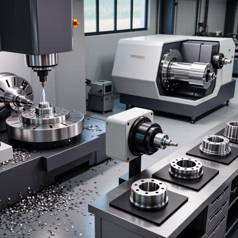
A complex part is not defined by shape alone. Its material, tolerance, surface finish, production volume, and inspection needs all affect which machining method is practical. A thin aluminum wall may distort under clamping, while a deep pocket can limit tool reach. Small details matter.
Read the drawing alongside the part’s intended use. Identify critical dimensions, datum surfaces, and features that must stay aligned. A tight tolerance on a bearing seat may justify a finishing pass, but applying that tolerance everywhere can add cost without improving function. Check whether internal corners, narrow slots, or angled faces require special tools or extra setups. Every repositioning can introduce alignment error.
Then compare these requirements with real shop constraints: machine travel, spindle access, workholding, tool availability, and inspection equipment. Hard materials can increase cutting time and tool wear; long, slender tools may chatter in deep cavities. It is tempting to choose a process from the model alone. That assumption can fail. A machinist’s review of the setup and cutting sequence often reveals risks before the first chip is made, though early estimates may still change after a test cut.
Compare common processes against practical requirements when selecting a method for a complex metal part.
Illustrative screening scores from 1 (low) to 5 (high), based on typical process characteristics—not guaranteed machine specifications. Actual results depend on material, part geometry, tooling, workholding, and inspection requirements. Use the comparison to shortlist processes, then confirm capabilities with a manufacturing engineer.
Choosing a machining method starts with the part’s geometry, not the machine’s advertised precision. A milled aluminum housing with open pockets may be straightforward on a three-axis mill. Undercuts or angled features can require extra setups or multi-axis movement. Each setup adds handling time and another chance for alignment error.
Turning suits round parts, such as a steel shaft with several diameters. For narrow slots or sharp internal corners in conductive materials, electrical discharge machining can reach shapes that cutting tools may struggle to access. It is usually slower, though, and does not suit every material. Material behavior matters, too: stainless steel can generate heat during cutting, while softer plastics may deform if clamped too firmly. Small details.
Tolerances should reflect how the part works, not how impressive a drawing looks. A bearing seat may need a tight diameter and controlled surface finish; a nonfunctional cover often does not. Tighter limits can require slower cuts, additional inspection, and more rejected parts. That cost is easy to underestimate. Before choosing a process, check tool access, wall thickness, material condition, and the measurement method. A thin rib might look easy in CAD, yet chatter during milling can leave a rough edge. Sometimes the planned method needs revisiting.
Choosing a machining method for a complex part starts with its functional demands, not its shape alone. Measure required accuracy at critical interfaces, such as bearing seats or sealing faces. Five-axis milling can reduce repositioning errors and reach angled features in one setup. However, tight tolerances still depend on tool condition, thermal control, and stable fixturing. Inspect critical features. Probing can verify hole location before final finishing.
Surface finish changes the choice again. Fine milling may suit accessible walls, while electrical discharge machining can create sharp internal details. EDM often delivers excellent detail, but it removes material slowly and may leave a recast layer requiring inspection. A polished appearance is not proof of good performance. I have seen parts with smooth surfaces fail because their flatness was never checked. That mistake is easy to repeat. Do not trust appearance.
Production volume adds a practical constraint. For one prototype, flexible CNC machining may be faster than building dedicated tooling. For thousands of parts, automated loading, repeatable fixtures, and shorter cycle times can outweigh a higher setup cost. Compare the full route, including programming, inspection, deburring, and rework. Speed alone can mislead. A method that wins on paper may struggle with chip evacuation or heat distortion. Run a small trial and record dimensional drift across the batch. That evidence is more reliable than a theoretical estimate. Still, I would question any process selected without reviewing the drawing, material, and inspection plan together.
| Machining method | Typical dimensional accuracy | Typical surface finish (Ra) | Complex-part capability | Speed and setup considerations | Best-fit production volume | Common selection trade-off |
|---|---|---|---|---|---|---|
| 3-axis CNC milling | About ±0.025–0.10 mm for many jobs; tighter tolerances may require careful process control. | About 0.8–3.2 μm as machined, depending on tool, material, and cutting conditions. | Good for prismatic parts, pockets, slots, and features accessible from a limited number of directions. | Usually straightforward to program and set up; multiple setups can add time and alignment risk. | Prototypes through medium production runs. | Cost-effective and versatile, but less efficient when features require many orientations or deep, narrow access. |
| 5-axis CNC milling | About ±0.01–0.05 mm is achievable on suitable parts and equipment; part geometry and setup affect results. | About 0.4–3.2 μm, with finer finishes possible through additional finishing operations. | Very good for contoured surfaces, angled features, and parts that benefit from access on multiple sides. | Can reduce repositioning and combine operations, though programming and machine setup are more demanding. | Prototypes through medium or high-value production runs. | Can improve access and reduce setup errors, but machine time and programming costs may be higher. |
| CNC turning | About ±0.01–0.05 mm for typical turned features, depending on material, geometry, and inspection requirements. | About 0.4–3.2 μm for common turning operations. | Excellent for rotational parts such as shafts, pins, bushings, and threaded components; limited for non-rotational features unless combined with milling. | Fast for repeated rotational features; bar feeding and automated loading can shorten cycle time on repeat work. | Low to high volumes, especially for repeatable rotational parts. | Highly productive for axisymmetric geometry, but not a standalone solution for many complex non-rotational features. |
| Wire EDM | About ±0.005–0.02 mm is common for precision work, subject to thickness, material, and finishing passes. | About 0.2–1.6 μm, depending on the number of skim cuts and process settings. | Excellent for intricate through-profiles, narrow slots, sharp internal corners, and electrically conductive materials. | Cutting is generally slower than conventional milling; setup and threading add time, while hard materials can be cut without conventional cutting forces. | Prototypes and low-to-medium volumes of precision parts or tooling. | Provides precise profiles with little cutting force, but requires conductive material and is less suited to rapid bulk removal. |
| Sinker EDM | About ±0.005–0.02 mm for suitable cavity work; electrode wear and setup influence accuracy. | About 0.2–3.2 μm, depending on roughing and finishing conditions. | Useful for deep cavities, ribs, and internal shapes that are difficult to mill, including in hardened conductive materials. | Requires a shaped electrode; electrode manufacture and electrical discharge time add to lead time. | Low-to-medium volumes, especially for dies, molds, and specialized cavities. | Can produce hard-to-reach cavities, but electrode design and wear increase process planning requirements. |
| Surface grinding | About ±0.002–0.01 mm for suitable flat features and controlled conditions. | About 0.1–0.8 μm, depending on abrasive, material, and finishing parameters. | Best for flat surfaces, parallel faces, and precision finishing; limited for complex three-dimensional geometry. | Often used as a finishing step after material removal by another process; setup and dressing are part of the cycle. | Low-to-high volumes for parts with precision flat surfaces. | Can deliver fine finish and close flatness control, but removes material slowly and is geometry-specific. |
| Metal additive manufacturing with machining | As-built features are often around ±0.1–0.3 mm; critical surfaces typically need machining for tighter tolerances. | As-built surfaces are commonly about 5–25 μm Ra; machined surfaces can be substantially smoother. | Excellent for internal channels, lattice structures, and consolidated designs; inaccessible internal surfaces may be difficult to finish or inspect. | Build time depends on part size, orientation, and layer settings; support removal and post-processing add time. | Prototypes and low-to-medium volumes of geometry-driven parts. | Enables shapes that are difficult to cut conventionally, but often needs post-processing and may not suit simple high-volume parts. |
Complex parts demand more than a capable machine. Tool selection, fixture design, and axis planning must work as one system. In shop trials, I have learned that cutting tool rigidity often matters more than maximum cutting speed. A short, stable tool reduces chatter around deep pockets and thin walls. Choose tool geometry according to material, corner access, and chip evacuation. Small details matter.
Fixtures should support the part without hiding critical surfaces. Use broad contact areas for thin components, but avoid excessive clamping force. It can distort the part before cutting begins. Modular locating pins can improve repeatability, especially when several setups are required. Still, every fixture needs a physical trial. Digital models do not reveal every loading problem.
Multi-axis machining can reduce setups and improve surface continuity. A five-axis strategy may reach angled features with fewer interruptions. However, more axes do not automatically produce better parts. Poor tool-axis control can leave marks near blended surfaces. I prefer testing the toolpath on a simplified model, then checking clearance, tilt limits, and holder access. Measure the first part at functional points, not only at easy edges. I once trusted a smooth simulation and missed a collision risk near a hidden rib. That mistake changed my review process. Slower verification is often cheaper than a damaged fixture. Controls must remain practical, documented, and repeatable across operators.
A promising machining route is only a hypothesis until it produces acceptable parts repeatedly. Run a controlled trial using the intended material, stock size, tooling, and fixture. Measure critical features with calibrated equipment, then record cycle time, scrap, tool wear, and setup effort. A single good part proves little. Repeat the run, including a tool change or restart, to expose variation that a polished first article can hide.
Compare methods using cost per conforming part, not machine-hour rate alone. Include programming, fixtures, inspection, finishing, and expected scrap. The 2024 Deloitte and Manufacturing Institute survey found that 92% of manufacturing executives viewed smart manufacturing as a key competitiveness driver over the next three years. That supports capturing test data digitally, but it does not prove automation will pay off for every part. For a short batch, a slower setup may still cost less.
Build a small cost model from measured results and realistic production volume. Test best-case and worst-case assumptions, especially yield and tool life. Then review the numbers with operators and quality staff; spreadsheet estimates often miss awkward chip removal or lengthy deburring. I have seen a technically elegant route lose its advantage at inspection. That deserves a second look. Keep the trial records, assumptions, and acceptance limits together, so later changes can be judged against actual evidence.
Complexity depends on material, tolerance, surface finish, volume, and inspection needs. Shape alone is not enough. A thin aluminum wall may bend during clamping.
Check critical dimensions, datum surfaces, aligned features, internal corners, narrow slots, and angled faces. A bearing seat may need a finishing pass. Do not apply tight tolerances everywhere without a functional reason.
Review machine travel, spindle access, workholding, tooling, and inspection equipment. Deep pockets may require long tools, which can chatter. Every repositioning may introduce alignment error.
A promising route remains a hypothesis until it makes acceptable parts repeatedly. Use the intended material, stock size, tooling, and fixture. One successful part proves little.
Measure critical features with calibrated equipment. Record cycle time, scrap, tool wear, setup effort, and dimensional variation. Include a tool change or restart.
Compare cost per conforming part, not machine time alone. Include programming, fixtures, inspection, finishing, deburring, and expected scrap. The cheapest hourly rate may not produce the lowest real cost.
Production volume, yield, tool life, and setup duration can change the result. A slower setup may cost less for a short batch. That assumption needs checking.
Spreadsheet estimates may miss difficult chip removal, awkward deburring, or lengthy inspection. Operators can identify setup risks before production. The model may still be wrong.
Keep trial results, assumptions, acceptance limits, tool information, and inspection data together. Use actual evidence when reviewing later changes. A polished first article can hide variation.
Choosing the right process for a complex part begins with understanding its geometry, material, tolerance requirements, and functional demands. Compare available machining methods by how well they can reach intricate features, maintain dimensional accuracy, and deliver the required surface finish. Consider production speed and volume as well: a method suited to a one-off component may not be efficient for a larger production run. Asking “which machining method is best for complex parts” has no single answer; the best choice depends on balancing these requirements.
Tool selection, secure fixturing, and multi-axis strategies can help reduce repositioning and improve consistency, particularly when a part has features on multiple sides. Before committing to production, validate the proposed method with testing and inspect the results against the design specifications. A final cost analysis should account for setup, machining time, tooling, and quality control, helping identify an approach that is both technically reliable and economically practical.

Nuplanta CNC