CNC machining can produce precise parts, yet small process errors often create visible and costly defects. A rough edge, undersized hole, or heat-darkened surface may begin with one overlooked setting. In a busy workshop, an incorrect tool offset can affect an entire batch before inspection detects the problem.
Many manufacturers ask, “what are common defects in CNC machining processes,” when parts fail dimensional checks or perform poorly during assembly. Typical issues include chatter marks, burrs, tool wear, poor surface finish, inaccurate dimensions, taper, and thermal distortion. These defects rarely have one simple cause. Material hardness, tool geometry, coolant flow, spindle speed, feed rate, fixturing, and operator judgment can interact in unexpected ways.
Prevention starts with disciplined preparation and honest observation. Reviewing tool-life records, checking workholding pressure, and measuring the first completed part can reveal risks early. A machinist may hear a change in cutting sound before a probe detects dimensional drift. That practical experience matters, but it should support documented procedures rather than replace them.
No process is perfect. Even a validated program can struggle after a material batch changes or coolant becomes contaminated. The seven methods in this guide focus on controllable actions, from selecting suitable cutting parameters to improving inspection routines. They are not shortcuts. They provide a reliable framework for reducing defects, protecting tolerances, and learning from failures before they become expensive production problems.
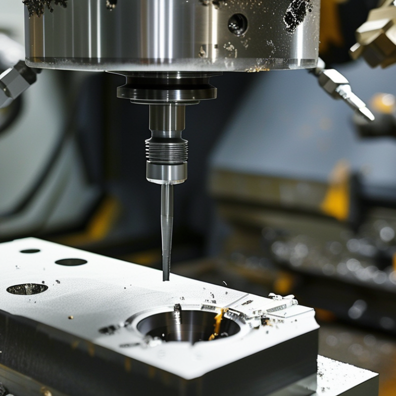
CNC machining defects usually begin with a small process change, not a sudden machine failure.
Burrs often indicate excessive tool wear, incorrect cutting parameters, or weak workholding. Chatter leaves repeating waves on the surface. It commonly comes from poor rigidity, excessive tool reach, or an unsuitable spindle speed. Dimensional drift can develop when heat builds in the tool, fixture, or workpiece.
The root cause is not always visible at the cutting edge. A dull tool may produce oversized holes, rough walls, and unusual cutting noise. Inadequate chip evacuation can recut chips and damage the finished surface. Thermal expansion creates another problem, especially during long cycles or tight-tolerance work. Measuring only the final part can hide when the error started.
Check tool offsets, temperature, coolant flow, and fixture pressure during production.
I once treated a rough finish as a feed-rate problem. The actual cause was a loose fixture contact. That mistake reinforced a useful lesson: inspect the whole process.
Record tool life, spindle load, vibration, and measured dimensions. Compare these records with the first acceptable part. A trial cut may look correct while later parts drift.
Workholding should be checked again, even when it appears stable. Small chips under a locating surface can shift the workpiece by several hundredths of a millimeter.
Conservative parameter changes are safer than changing several variables at once.
Preventing CNC defects starts before the spindle turns. Match material hardness and heat behavior to the cutting method. Aluminum may smear with a dull edge, while hardened steel can overload a fragile tool. Inspect the stock for scale, warping, and inconsistent thickness. A flat, clean blank reduces vibration and unexpected depth errors. Choose tools with suitable geometry, coating, diameter, and reach. Shorter tools usually resist chatter better. They are not always accessible, though.
Set spindle speed, feed rate, and cutting depth from material data and machine behavior. Do not copy a chart blindly. A rigid machine may accept heavier cuts than a lighter setup. Reduce radial engagement when thin walls begin to ring. Adjust coolant flow so chips leave the pocket instead of recutting. Dry cutting can work for some materials, but heat often tells a different story. Listen for squeal. Check chip color.
Secure the workpiece carefully, then verify tool offsets and work zero with a probe or gauge. A few tenths of error can ruin a finished face. Use simulation and first-piece inspection to catch collisions, burrs, taper, and poor finish early. Even a careful setup can fail after tool wear or a blocked nozzle. Inspect edges, chips, and dimensions during the run, not only afterward. I have seen a perfect first pass hide a weak clamping point. Rechecking felt slow, but skipping it would have been slower.
Cutting parameters decide whether a CNC part shows burrs, chatter, or a polished edge. In practice, I adjust feed per tooth before changing spindle speed. Excessive feed leaves visible scallops, while excessive speed can soften the cutting edge. A 2022 review in the Journal of Manufacturing Processes identified cutting speed, feed rate, and tool wear as major surface-roughness factors. The theoretical roughness also rises sharply with feed, following the relation Ra ≈ f²/(32r). Small changes matter.
Use a stable starting point from the tool maker’s cutting chart, then test one variable at a time. Record spindle speed, feed, radial engagement, coolant condition, and measured Ra. ISO 21920-2:2021 provides methods for evaluating surface texture, while ISO 230-2:2014 covers machine-tool positioning accuracy. These standards support reliable checks, but they do not replace shop-floor judgment. I have seen a perfect first pass hide gradual tool wear. That mistake is easy.
Tips: Reduce radial engagement when chatter appears. Lower feed when burrs form on thin walls. Watch the chip color and shape. Measure the part after thermal stabilization. Keep a short trial log. It may feel slow, but repeatability improves. One limitation remains: published data often uses ideal laboratory setups, unlike a warm machine, interrupted cuts, or uneven stock. Recheck parameters under actual production conditions.
Correct spindle speed is essential for reducing chatter, burrs, poor surface finish, tool wear, and dimensional errors. The chart shows the calculated spindle speed for different tool diameters at a cutting speed of 150 m/min. Values are based on the standard formula: RPM = (1000 × cutting speed) ÷ (π × tool diameter).
Use the calculated RPM as a starting point, then fine-tune feed rate, depth of cut, coolant flow, tool geometry, workholding, and tool condition according to the material and machine rigidity. Keeping cutting parameters within a stable range helps achieve accurate dimensions and a smoother surface finish.
Applying Proper Workholding, Cooling, and Chip Control Methods
Reliable machining starts with stable workholding. Tighten the fixture evenly, clean every contact surface, and check that the workpiece sits fully against its stops. A small chip under the part can create taper, vibration, or incorrect dimensions. Use soft jaws when surface damage matters. For thin sections, add support close to the cutting zone. Excessive clamping force can also distort the part. This is easy to overlook.
Cooling affects both accuracy and tool life. Aim the coolant directly at the cutting edge, not merely at the general machining area. Use enough flow to remove heat and prevent chips from welding to the tool. For deep pockets, adjust the nozzle as the tool moves. Air can help clear shallow cavities, but it may scatter hot chips. Temperature changes still deserve attention. A stable process is not always a perfectly cold process.
Chip control completes the setup. Choose cutting conditions that produce short, manageable chips, then guide them away with coolant, air, or a suitable toolpath. Never allow chips to recut inside a pocket. Inspect flutes, walls, and corners during the run. If a finish looks rough, do not immediately blame the tool. Poor evacuation or weak workholding may be the real cause.
Tips: Mark the fixture’s contact points, verify nozzle direction before cutting, and pause after the first pass to inspect chip shape. Record what worked. Some adjustments will fail, and that result can reveal more than a lucky first attempt.
Recurring CNC defects rarely begin at final inspection. They often start with tool wear, thermal drift, poor workholding, or contaminated coolant. Inspect the first piece against the drawing, then repeat checks during the run. Measure critical diameters, hole locations, surface finish, burrs, and flatness. Record actual values, not only pass or fail results.
Statistical process control can expose gradual movement before scrap increases. Use control charts for dimensions that affect assembly. Check the measuring system regularly, because an inaccurate gauge can create false confidence. Deloitte’s 2023 Global Smart Manufacturing Survey found that 86% of manufacturers viewed smart manufacturing as a major future competitiveness driver. The value depends on disciplined data collection. A dashboard cannot repair careless inspection.
Maintenance must follow the defect pattern. Check spindle vibration, backlash, axis lubrication, coolant concentration, chip evacuation, and fixture repeatability. Calibrate probes and measuring equipment on schedule. The U.S. Department of Energy’s Operations & Maintenance Best Practices Guide reports that preventive maintenance can reduce maintenance costs by 12–18% compared with reactive work. Still, scheduled maintenance is not enough. I have seen teams replace cutting tools while ignoring thermal changes after long production cycles. That mistake can repeat for weeks. Review inspection records with maintenance logs, identify the earliest abnormal signal, and document the corrective action. A weak point remains: operators may record measurements after adjustment, not before it. Capture both.
| No. | Prevention Method | Common Defect Controlled | Typical Root Cause | Inspection or Maintenance Action | Recommended Frequency | Practical Success Indicator |
|---|---|---|---|---|---|---|
| 1 | Verify the CNC program and work offset | Incorrect dimensions, wrong hole location, excessive material removal | Incorrect tool offsets, wrong work coordinate, outdated revision, or programming error | Use simulation or dry runs, confirm the active program revision, check tool length and diameter offsets, and verify work coordinates against the setup sheet before cutting. | Every setup and program revision | First-off part matches the drawing’s critical dimensions and datum locations. |
| 2 | Inspect cutting tools and control tool wear | Oversize features, poor surface finish, burrs, chatter, and dimensional drift | Worn, chipped, dull, or incorrectly selected tools; excessive tool runout | Inspect cutting edges, measure tool runout when required, monitor tool life, replace damaged tools, and use conservative cutting parameters for difficult materials. | Before each job; during production at defined intervals | Stable dimensions and surface finish throughout the tool-life interval. |
| 3 | Maintain proper workholding and part alignment | Taper, positional error, distortion, vibration, and inconsistent thickness | Insufficient clamping, dirty locating surfaces, jaw wear, poor support, or workpiece movement | Clean contact surfaces, check fixture condition, confirm locating pins and stops, apply consistent clamping force, and support thin or flexible sections. | At every setup; recheck after any suspected movement | Repeatable datum alignment and no visible movement during machining. |
| 4 | Control coolant flow and chip evacuation | Built-up edge, overheating, scratches, recutting marks, and premature tool failure | Blocked nozzles, contaminated or insufficient coolant, poor chip evacuation, or chips trapped in the cut | Check coolant concentration according to the coolant supplier’s specification, clean filters and tanks, aim nozzles at the cutting zone, and remove chips regularly. | Each shift; coolant checks according to the maintenance schedule | Consistent chip shape, controlled cutting temperature, and clean machined surfaces. |
| 5 | Calibrate measuring equipment and inspect critical features | Undetected out-of-tolerance dimensions and false acceptance or rejection | Uncalibrated gauges, incorrect measurement technique, temperature effects, or unsuitable measuring range | Use calibrated instruments, select the correct gauge for each feature, clean measuring faces, control measurement temperature, and record critical measurements. | Before use; calibration at a documented interval | Measurement results are traceable, repeatable, and within the specified uncertainty. |
| 6 | Check machine geometry and thermal stability | Machine-related positional error, taper, circularity error, and dimensional drift | Thermal expansion, backlash, misalignment, worn guides, spindle issues, or inadequate warm-up | Warm up the machine when required, monitor ambient and spindle temperature, inspect axis backlash, verify spindle condition, and perform scheduled geometric checks. | At startup when required; periodic preventive maintenance | Stable geometry from the first part through the full production run. |
| 7 | Use documented root-cause analysis and corrective action | Recurring defects, inconsistent process performance, and repeated rework | Temporary adjustments without identifying the underlying process cause | Record defect type, machine condition, tool data, material lot, operator observations, and measured values; use trend charts or Pareto analysis, then verify the corrective action on subsequent parts. | For every nonconformance; review trends weekly or by production batch | Reduced repeat defects, lower scrap and rework rates, and verified corrective-action effectiveness. |
: Burrs often come from tool wear, excessive feed, or weak workholding. Lower feed on thin walls. Check the cutting edge and fixture contact.
Chatter usually indicates poor rigidity, excessive tool reach, or unsuitable spindle speed. Reduce radial engagement and shorten tool reach when possible. Listen for a repeating cutting sound.
Heat can expand the tool, fixture, or workpiece. Measure parts after thermal stabilization. Check temperature, coolant flow, and tool offsets during production.
A dull tool may create oversized holes, rough walls, and unusual cutting noise. Inspect the tool before changing several cutting parameters. Noise can be an early warning.
Poor chip evacuation can recut chips against the finished surface. A loose fixture can also create roughness or movement. I once blamed feed rate. I was wrong.
Start with a stable cutting chart from the tool supplier. Change one variable at a time. Adjust feed per tooth before changing spindle speed.
Record tool life, spindle load, vibration, coolant condition, and measured dimensions. Compare each result with the first acceptable part. Final inspection alone may hide the process change.
Yes. Small chips under a locating surface can shift a workpiece by several hundredths of a millimeter. Check fixture pressure and contact areas again. It may look stable.
Tool wear may appear only after several parts. A warm machine may also change dimensions gradually. A trial cut can fool you. Keep a short production log.
This guide explains what are common defects in CNC machining processes, including dimensional inaccuracies, poor surface finish, burrs, chatter marks, tool wear, deformation, and incorrect hole or feature locations. It focuses on identifying the root causes of these problems, such as unsuitable materials, worn or inappropriate tools, unstable machine settings, excessive cutting force, poor workholding, inadequate cooling, and ineffective chip removal.
The article presents seven practical ways to prevent recurring defects. These include selecting compatible materials and tooling, optimizing spindle speed, feed rate, and cutting depth, securing the workpiece properly, using suitable cooling and lubrication, and controlling chips during machining. It also emphasizes systematic inspection through dimensional checks and surface evaluation, along with regular cleaning, calibration, and maintenance of equipment. By combining accurate process planning with continuous monitoring, manufacturers can improve precision, surface quality, productivity, and overall machining reliability.
Nuplanta CNC